Introducing the DIY Robot Arm controlled by Human Gestures.
Imagine being able to control a robotic arm with just the movement of your hand, mimicking the synergy between humans and machines seen in blockbuster films like Pacific Rim or Avatar. While we’re not quite at the level of industrial-sized robots yet, what if you could build a smaller, functional version that responds to your gestures?
This project is an attempt to achieve this.
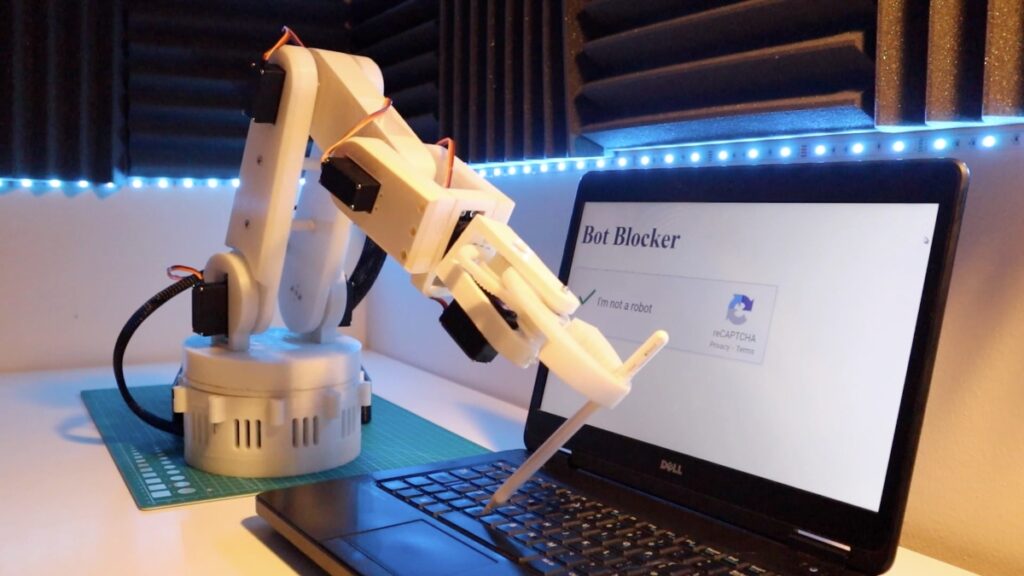
We’re taking on the challenge of building an Arduino-powered robotic arm, designed to follow hand gestures in real-time. Whether it’s rotating, grabbing objects, or performing complex maneuvers, this robotic arm can be programmed to carry out tasks with precision, all through the natural movements of your hand.
Staying true to Iron man’s suit convention, each iteration would be known as Mark. This prototype would be known as MARK 1. We can expect more iterations to improve on the original robotic arm.
View the Full DIY Robot Arm (controlled by Hand Gestures) Tutorial Here
Overview
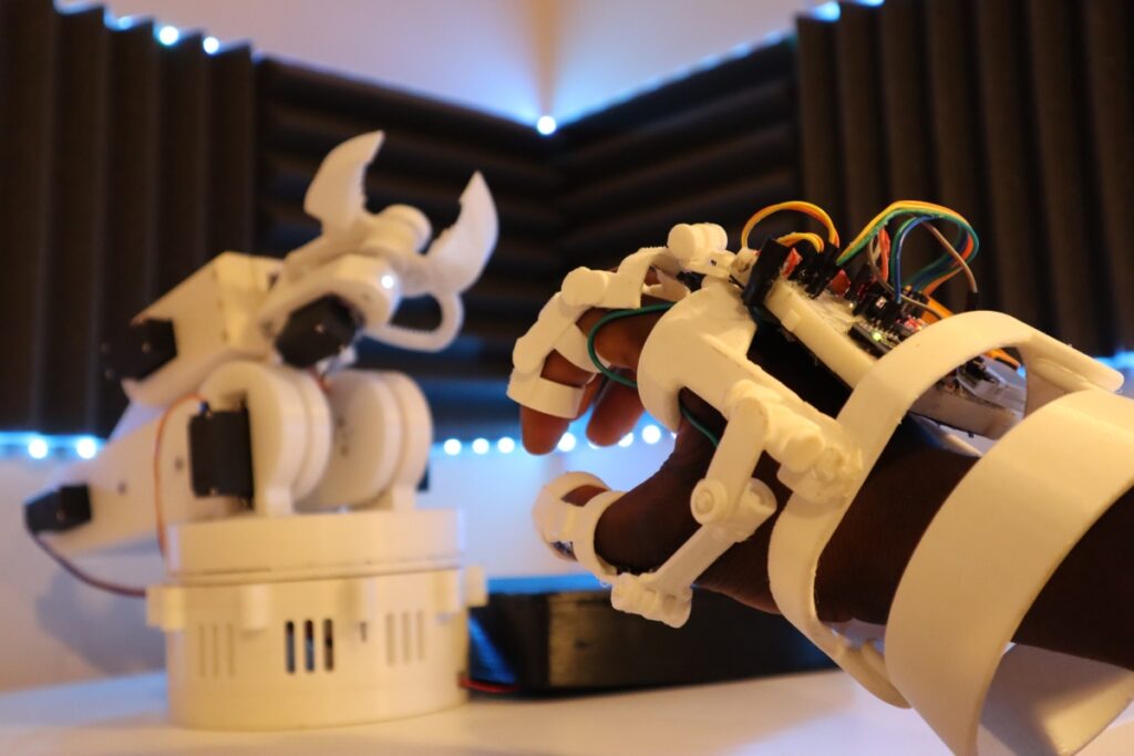
In this tutorial, we’ll build a six-axis Robot controlled by Hand gestures using a Robotic Glove. And by mimicking natural human gestures such as a pinch, or a wrist rotation to the left, You’ll be able to open/close or rotate the robotic arm left and right respectively. In effect, manually controlling a Robotic Arm.
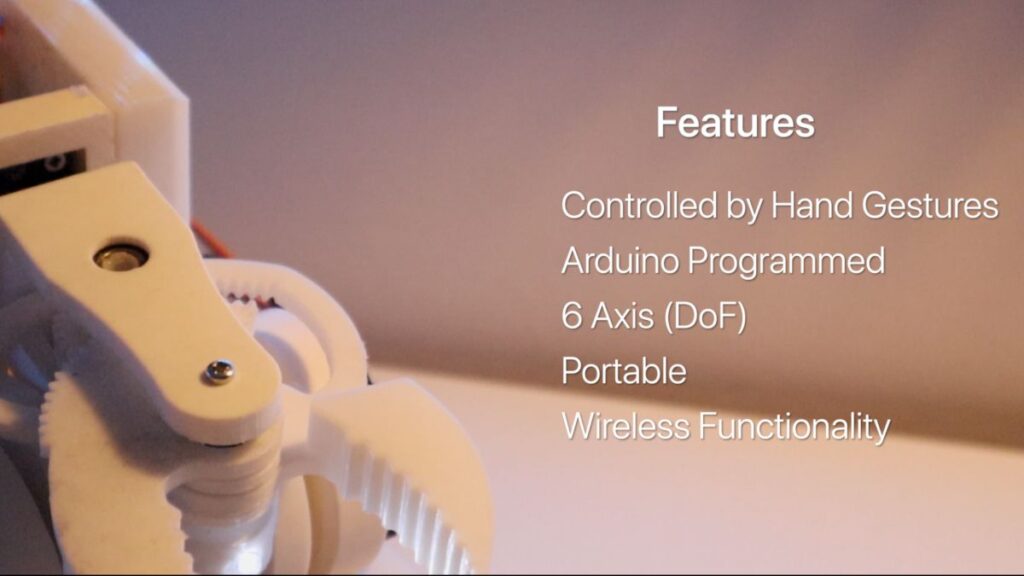
MARK 1 Features:
- 6 Axis Rotation
- Portable
- Control the Robot with Human Gestures
- Can Be pre-programmed to carry out basic functions
- Can be controlled wirelessly from a range
- Can hold a load weight 600g (Max Load 1kg)
Part List
The Robotic Arm is fully customizable. You can either buy your own or 3d print your own. If you choose to 3D print, no worries. There is a list of different Robots that use servo motors, so the theory of what we’re building still applies.
For this project, this prototype (Mark 1) would be 3D printed as it gives me more space to create custom parts.
Robotic Arm: Thingiverse 3D Printed Robotic Arm (credits: Wonder Tiger):
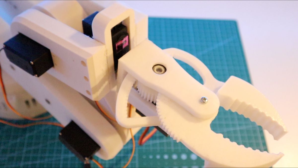
- Part 1: Gripper Parts
- Part 2: Base and Turntable
- Part 3: Robotic Core Arm
You can find more information on this build, along with the screw types from the parts above. The time taken to print can up to 40 hours. However, this cuts the cost of buying a Robotic Arm.
Robotic Glove: The Robotic Glove.STL files (credits: Roman 13)
The Robotic Glove was an aesthetic addition to the project, but you can just as well use a builders glove to implement the Robotic Arm.
Note: for larger hands, print at 105% scale
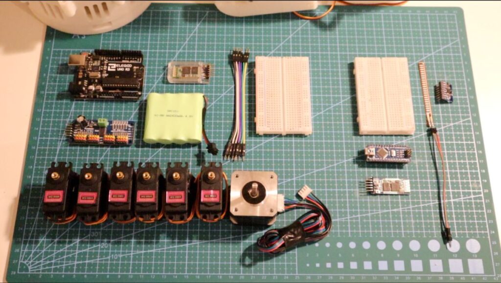
Robotic Arm – Electronics
Below are all the parts that are required to build the electronics:
Hand Glove – Electronics
Accessories – Electronics
| Other Parts |
| Braided Sleeve |
| Breadboard |
| Jumper Wires |
How it Works
Overall, we’re sending a signal (over Bluetooth) from the Robotic Glove to the servo motor. When a value has been received, the servo driver will send a signal to a specific servo motor moving the Robotic Arm.
Now, if we add multiple servos and more sensors, we can control each Motor. `
If we think of a Robotic Arm as a series of servo motors coordinating with each other to perform a function, we can create a robotic arm controlled by a Robotic glove.
The Robotic Glove’s Arduino uses sensors to communicate with the Robotic Arm Arduino and sends data to move a Servo to the desired angle.
You may be wondering, what sensors does the Robotic Glove use?
For MARK 1, we would be using Flex Sensors and an accelerometer (MPU6050)
- Flex Sensors – Based on the degree of bend of this plastic piece, the resistance changes, affecting the current. This measurement is then used to detect hand movement changes.
- Accelerometers – For more natural gestures, an accelerometer can detect a change in the arms and wrist rotation.
We are using these sensors to detect a change in a gesture. We can then send a specific value mapped of a gesture to the Robotic Arm to control a servo motor via Bluetooth. And With enough gestures, the robotic arm comes to life!
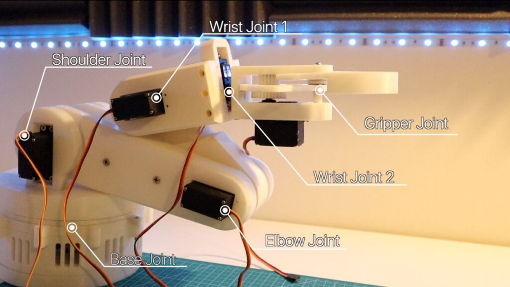
Robotic Arm Mapping
The following represents a mapping table of the values sent to the Robotic Arm by the Glove. Each is having keys to characterize its function. (P – Pinkie, L – Right, etc.)
| Number | Servo Name | Robotic Arm Action | Glove Sensor Values | Action |
| 1 | Base Joint | Rotate Base Left or Right | Acccelermotor_2 T, t | Move Elbow Left or Right |
| 2 & 3 | Shoulder Joint | Move Shoulder Joint Closer or Further | Pinkie Finger Flex – P, p | Bend or Extend Pinkie |
| 4 | Elbow Joint | Rotate Elbow Joint Closer or Further | Accelerometer_2 – C, c | Bend Elbow or Extend Elbow |
| 5 | Wrist Joint | Rotate Robotic Arm Joint Up or Down | Accelerometer_1 – U, D | Rotate Wrist Up or Down |
| 6 | Wrist Joint 2 (Rotate) | Rotate Robotic Arm (CW or CCW) | Accelerometer 1 – L, R | Rotate Wrist Left or Right |
| 7 | Gripper Joint | Close Claw Grip or Open Claw Grip | Index Finger Flex -F,f | Bend or Extend Index Finger |
Note: Capital “F” (finger) represents the opposite direction of the servo motor spin
Assembly of Parts
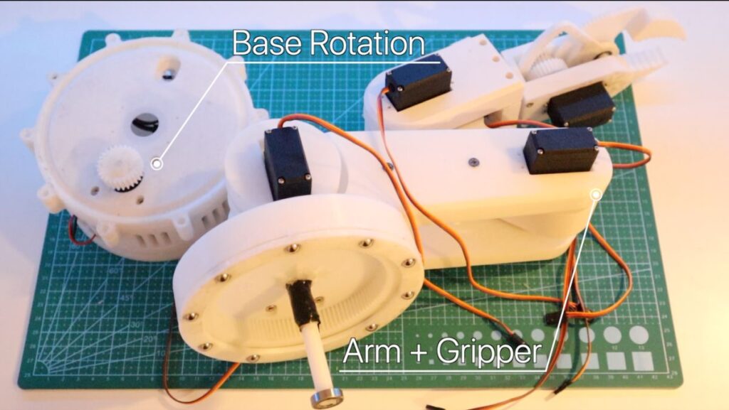 Robotic Arm – Assembly
Purchasing a Robotic Arm can be quite expensive. To to keep this robotic arm within Budget, 3D printing a Robotic Arm was the best option.
This helps in the long run, as there are many examples of a 3D printed robotic arm that can be customized, e.g., adding an LED, creating a camera stand Clamp:
As previously mentioned, the Robotic Arm was modeled around the Robotic Arm on Thingyverse. I’ve chosen this example as it was an excellent design providing six-axis, well documented, and had strength/ robustness. You can access Wonder Tiger’s Robotic Arm from the Part’s list.
You can also find my remixes for a Robotic Arm Camera Stand. We’ll cover this more in a future release. However, the parts could take a collect at least 40 hours to print all parts.
You can find many other Robotic Arm 3D Printed alternatives too.
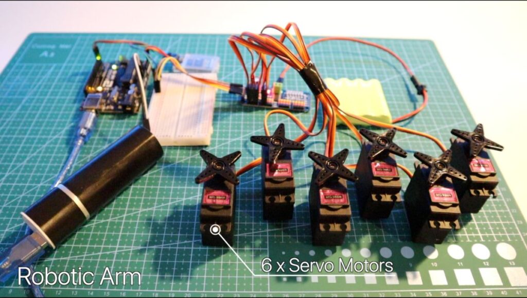
Introducing the servo motor and Driver
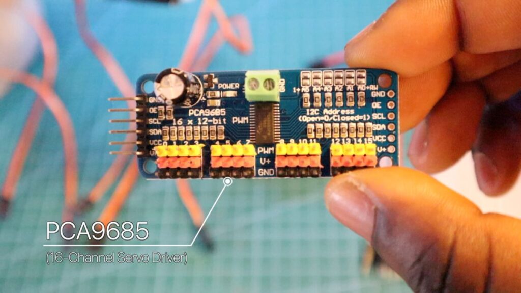
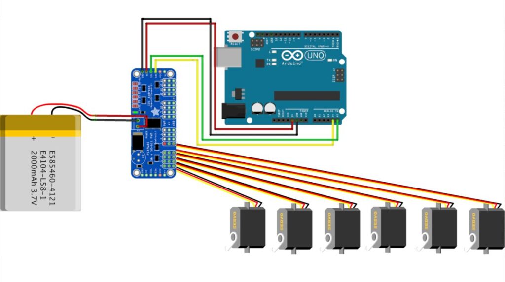
Given that the Robotic Arm is ideally a series of motors in coordinating together, we can theoretically attach several motors that can be all powered by the Arduino. In this project, we’ll be using the PCA9685 Servo Driver to power the MG966R Servo.
HCPCA9685 Library: Add this Library to your Arduino IDE.
Note: Use an external power supply when powering each Motor. The Arduino cannot supply enough power to control all motors. In this project, a 5V, a 2200 mAh RC Battery was used.
The Arduino diagram wiring should look as below:
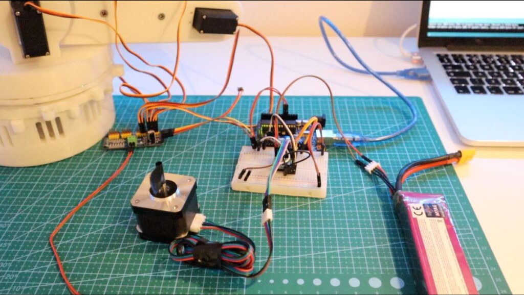
NEMA-17 for base rotation
Since the Robotic was starting to gain a bit of weight, and the MG966R servo motor was not powerful enough to rotate the Robotic Arm at the base. To rotate the Robotic Arm, a more robust motor than a servo motor would need to be used
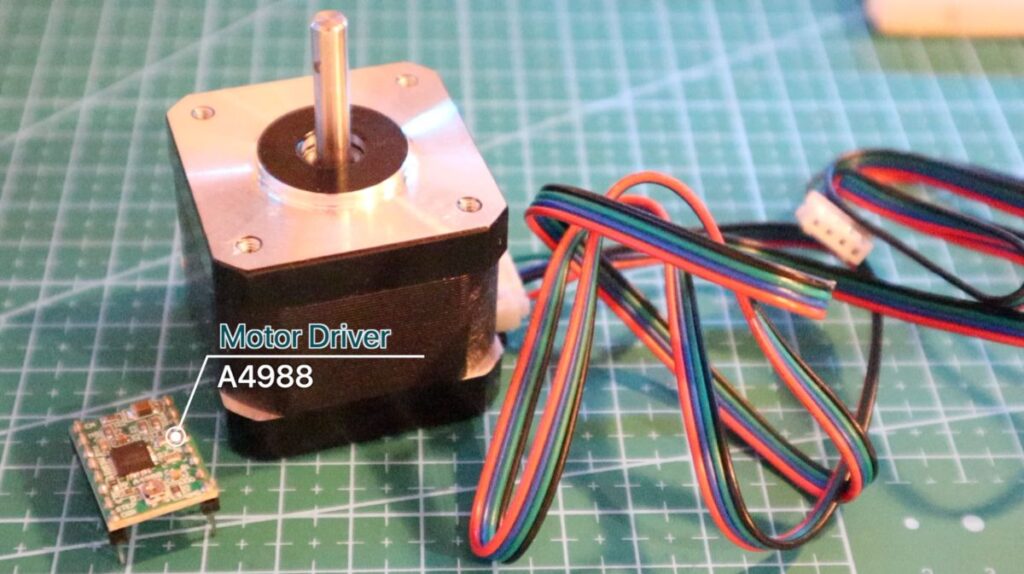
A Stepper Motor (NEMA-17) can be used due to its precision and high torque, helping the Robotic Arm rotate seamlessly to gesture controls.
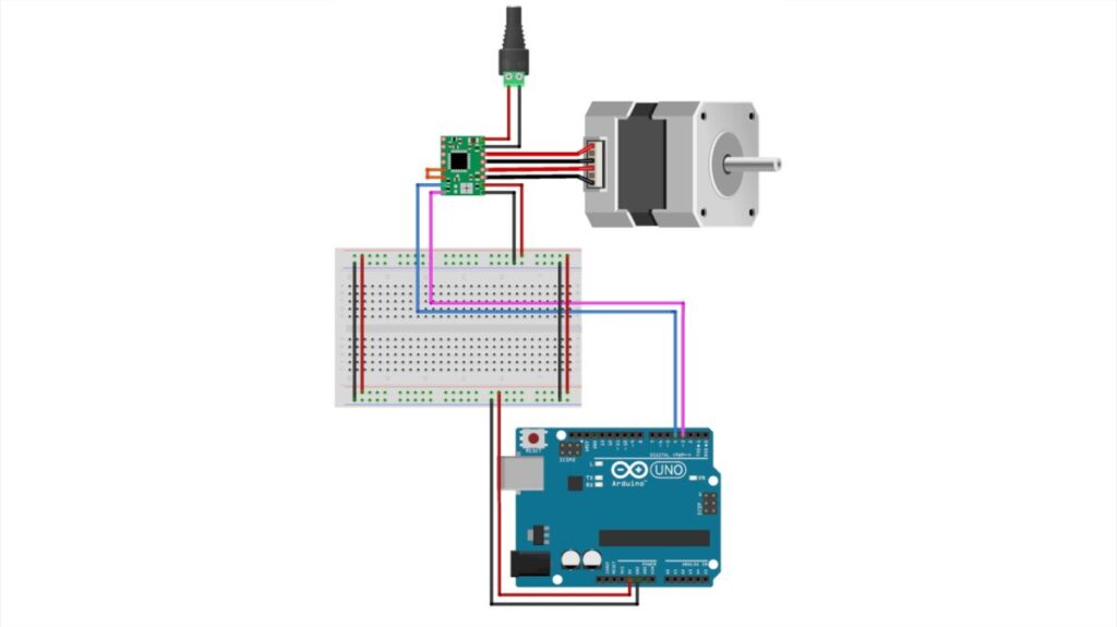
The NEMA-17 and the A4988 Driver si used to control the direction of the Motor, you can see from the diagram below:
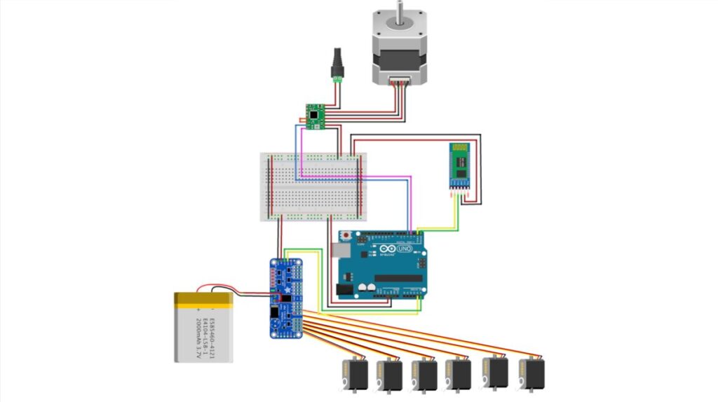
And finally, the following diagram shows the final wiring diagram assembly of the complete Robotic Arm.
Assembly of Circuitry
The below wiring diagram shows the final assembly of all electronic parts to create a Robotic arm, including the Bluetooth module. We’ll cover the paring process below.
Human Flex Sensor
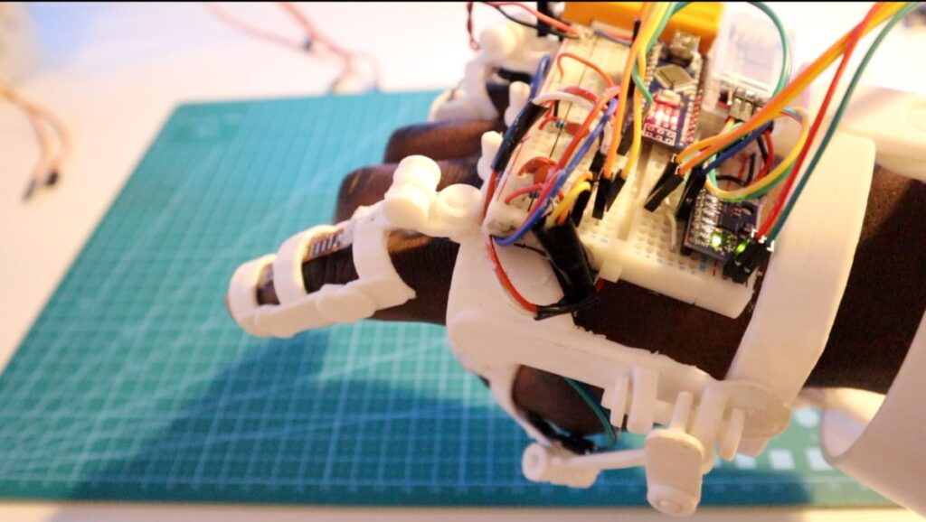
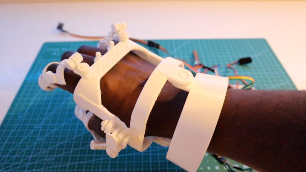
In keeping true to the Robotic Arm’s aesthetics, you can print a 3D Printed Exoskeleton Gauntlet to use as your Robotic Glove.
However, you can use a standard Builder’s Glove for prototyping the Robotic Glove. This ‘Robot Glove Exoskeleton’ design just blended well with the design of the Robotic Arm.
The Robotic Glove consists of the following components:
- Flex Sensor – Based on the bend of the finger, the current changes which we could use to send a signal to the Motor
- Accelerometer (MPU6050) – We can control the Motor by mapping human gestures from X, Y, Z plane
- LED – The LED will light up when a human gesture control has been sent to the Arduino
- Bluetooth (HC-05) Module – Sending data to Robotic Arm HC-05 Receiver
- Arduino Nano – The microcontroller would perform as the brains of the Robotic Glove
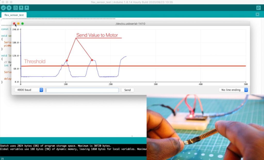
The following diagram is great to test the flex sensor and the Accelerometer.
Important: The Robotic Arm will only be as accurate as the robotic Glove controls, So it’s worth getting this right.
Configuring the Bluetooth (Master and Receiver)
The Arduino Robotic Arm communicates over Bluetooth using the HC-05 modules. Below highlight the critical information.
| Module | Configuration |
| Robotic Glove HC-05 | Master |
| Robotic Arm HC-05 | Slave |
Arduino Programming
You can download the following code below:
Note: All other test codes and the latest version can be found on the Arduino Robotic Arm Git Repo
Programming the Robotic Arm
The Robotic Arm code makes use of the HCPCA9685 Library (for the Servo Driver). This way, we can power multiple servo motors, all controlled by an Arduino. In the code, we can start by adding this library and declaring the servo variables.
The following variables are used to find the previous/increment and get the Servo’s current position.
* Include the HCPCA9685 library */
#include "HCPCA9685.h"
/* I2C slave address for the device/module. For the HCMODU0097 the default I2C address
   is 0x40 */
#define  I2CAdd 0x40
/* Create an instance of the library */
HCPCA9685 HCPCA9685(I2CAdd);
//initial parking position of the motor
const int servo_joint_L_parking_pos = 60;
//Degree of robot servo sensitivity - Intervals
int servo_joint_L_pos_increment = 20;
//Keep track of the current value of the motor positions
int servo_joint_L_parking_pos_i = servo_joint_L_parking_pos;
//Minimum and maximum angle of servo motor
int servo_joint_L_min_pos = 10;
int servo_joint_L_max_pos = 180;
Initialize the Serial Port at Baud Rate 4800 to start the Bluetooth communication
Serial.begin(4800); // Initialise default communication rate of the Bluetooth module
In the loop() section, we’re constantly checking whether any data is coming from the robotic glove. If true, we’ll store the incoming data in the ‘state’ variable. And depending on the character given, we’ll use this to move the motor(s).
The following section outlines the code:
The Robotic Arm code can be seen as a series of servo motors working together to simulate human movements. The code is the same, with Servo’s being driven by a Servo Driver based on Bluetooth’s values.
//Defining the servo driver. 0x40 Address is the default I2C Address.
#define I2CAdd 0x40
int response_time = 5; //Receiving values from the Robotic Glove interval
// Checks whether data is coming from the serial port

if (Serial.available() > 0) {
    state = Serial.read(); // Reads the data from the serial port
    Serial.print(state); // Prints out the value sent
    //Motor functionality code block
}
Based on the current ‘state’s value,’ the servo Driver would send a signal to the respective Motor.
For example, if we bend our fingers. The value ‘f’ would be sent by the robotic glove (via Bluetooth) whereby the Robotic Arm would read this data and trigger a function to rotate the respective servo motor. This process is repeated in an infinite loop.
if (Serial.available() > 0) { // Checks whether data is coming from the serial port
    state = Serial.read(); // Reads the data from the serial port
    Serial.print(state); // Prints out the value sent
    //For the naming of the motors, refer to the article / tutorial
    //Move (Base Rotation) Stepper Motor Left
    if (state == 'S') {
      baseRotateLeft();
      delay(response_time);
    }
}
Note: The code implements a hard stop, to stop the Motor from exceeding its maximum angle, which can strip the motor gears.
HCPCA9685.Servo(0, servo_joint_L_parking_pos_i); // Drive the servo motor at channel 0 to the desired angle.
//Move Claw Motor Downwards
    if (state == 'f') {
      if (servo_joint_3_parking_pos_i < servo_joint_3_max_pos) {
        HCPCA9685.Servo(4, servo_joint_3_parking_pos_i);
        delay(response_time);
        Serial.println(servo_joint_3_parking_pos_i);
        servo_joint_3_parking_pos_i = servo_joint_3_parking_pos_i + servo_joint_3_pos_increment;
      }
    }
void baseRotateLeft() {
    digitalWrite(stepPin, LOW); //Spin in a direction based on HIGH, LOW
    delayMicroseconds(stepDelay); //Change the speed of the Stepper motor
}
If the value of the servo motor is less than the maximum rotation, continue spinning. If it has reached the maximum rotation of 180 degrees, stop.
servo_joint_3_parking_pos_i < servo_joint_3_max_pos
Where servo_joint_3_max_pos is the maximum position of the Motor.
Note: The code implements a hard stop to stop the Motor from exceeding its maximum angle, which can strip the motor gears.
Programming the Flex Sensor
The Robotic Arm code can be found on GitHub. If you work on the project, contribute your own version to Git Repo. This would help build an index of different versions and functionalities of the Robotic Arm.
The code has already been documented (Also available on Git). However, we’ll cover the key points:
We’ll define the five sensors:
//LED ON PIN 3
int pinkie_Data = A1;
int finger_Data = A2;
int thumb_Data = A3;
//const int MPU_addr = 0x68;
const int MPU2 = 0x69, MPU1 = 0x68;
Note: 0x68 and 0x69 represent the I2C Address of the 2 MPU6050 Accelerometers
//How often to send values to the Robotic Arm
int response_time = 1000;
The Following code outlines the Arduino reading the values of the sensors:
  // read the values from Flex Sensors to Arduino
  pinkie = analogRead(pinkie_Data);
  finger = analogRead(finger_Data);
  thumb = analogRead(thumb_Data);
Read the current position of the Accelerometer:
GetMpuValue1(MPU1);
GetMpuValue2(MPU2);
Calibrating the values:
The Following code calibrates to find the upper and lower limit of the Flex Sensor. To re-calibrate the flex glove, press the reset button on the Arduino.
  if (bool_caliberate == false ) {
    delay(1000);
    thumb_high = (thumb * 1.15);
    thumb_low = (thumb * 0.9);
    finger_high = (finger * 1.03);
    finger_low = (finger * 0.8);
    pinkie_high = (pinkie * 1.06);
    pinkie_low = (pinkie * 0.8);
    bool_caliberate = true;
  }
We’ll constantly check if the current value has exceeded the defined flex’s upper or lower limit based on the calibration. If the flex sensor goes above or below this value, data is sent to the Robotic Arm to move a specific servo motor in a specific direction.
  // finger 1 - Claw Bend/Open
  if (finger >= finger_high) {
    Serial.print("F");
    delay(response_time);
  }
  if (finger <= finger_low) {
    Serial.print("f");
    delay(response_time);
  }
Programming the Robot Arm
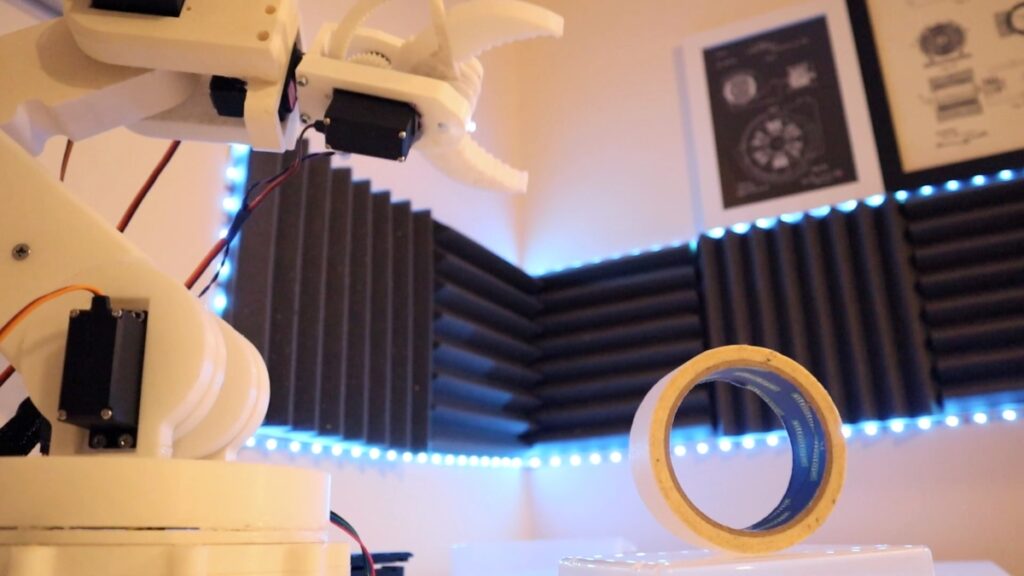
Results – Pay-off
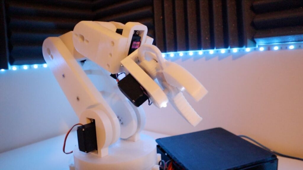
The Robotic Arm is accurate enough to move objects. However, it will require some work to move complex objects, or even compete with the ‘million-plus year’ human beings have on dexterity … although spending more time working on the code, the Robot’s precision can be is works as intended for MARK 1i. Although the Arm can be improved can be improved significantly.
If you would like to improve the code, contribute to the Arduino Robot Arm Git Repo and build your arm. Let’s make this open for others to build on!
Lastly, We can also control the Robot through hand gestures and program the Robot to automate basic tasks.
Next Steps
And that’s all for MARK 1 (Version 1) folks!
But this is just the beginning. With more iterations planned, there’s plenty of room to improve the arm’s dexterity, precision, and power. Plus, by integrating new technologies, you could take this project even further, perhaps adding advanced AI functionality or automation.
If you would like to support this project, consider supporting my Patreon page.
Alternatively:
Hey! I was wondering if i could just buy an arm and if you have any recommendations and which arm I could buy? I dont really have a 3D printer so was wondering if you know of any decent arms.
Hi Mo,
Thanks for watching. The best arm differs on your preference but I would recommend getting a servo motor Arduino Arm on Amazon. The best-rated one should be a good choice. You can pretty much then start from Arduino and programming building.
Hi, great project you did. I wanted to know if it was possible to have access to the electronic diagram to build the hand and be able to control the robotic arm. I saw that the arduino code is present but not the diagram. Also my 3d printer is not big enough for printing so I figured I could change the proportions and include 9g servo motors in it. Do you think this could work? Thanks in advance.
Hi Codev,
Sure, you can find the diagrams on my Git with code and all:
https://github.com/EbenKouao/arduino-robot-arm
Hope this helps.
Eben.
I am very impressed by this project and plan to give it a go. I have a 3D printer so that helps. i am a 75 year old Englishman and my electronics training was on thermionic valves and transistors (a long time ago) so I am looking forward to using ths project to learn about the new world….and it is ideal for Covid lockdown! Thanks very much and I hope your career goes from strength to strength!
Hi Trevor,
Thanks and much appreciated!!
Hope you find these projects useful. More interesting projects on the way.
Stay tuned!
Is there an alernative to the LiPO battery. It needs an expensive charger and I am sure a 9v battery should be OK?
Hi Trevor,
You could use a 9V battery, but the capacity would not be as much…(assuming you’re referring to the 12V NEMA 17 Motor)
If you would like to use an alternative have a look at a 12V RC Battery
Good luck!
i cant find hcpca9685 library . where i find this library?
Hi Cagatay,
You can find it here in AdaFruit GitHub: https://github.com/adafruit/Adafruit-PWM-Servo-Driver-Library
Are you using a continuous servo? I bought the MG996R and they seem to operate like continuous servos which doesn’t allow me to use them for inverse kinematics.
Hi Michael, seems you’ll need to use the 180 degrees Servo Motor versions (the one used for this Arm). This would help you set a fixed position.
Dear Eben,
Hello.
I want to thank you for you job. It is great.
I have almost repeated your project ( robot arm). But I have several problems with it. And I still can not to force it to work property. I have finished the hardware but can not cope with a code because I am not good at programming.
I would be appreciate you a lot if you connected with me by email and help me a little bit to complete this project. First of all I would ask you to share the working code ( arm+ glove) version wich does not need any adjustments. As I noticed the code which you placed at Github should be adjusted before using.
I hope you will answer. Thx in advance.
Hi Vlad,
You can use the code in the Arduino Robotic Glove:
https://github.com/EbenKouao/arduino-robot-arm/tree/master/code comment out the debugFlex().
This should allow you to send data based on the flex sensor. Keep in mind to wear the glove before turning it on as this would take the initial reference position.
Hope this helps, Thanks.
Eben.
Hello,
Could you share the last working version of the code (glove + arm)?
Current version does not work.
I would be appreciate a lot.
Hi Vlad,
You can find all the code on GitHub: https://github.com/EbenKouao/arduino-robot-arm/tree/master/code
Back on this after a delay. Can’t find the HCPCA9685.h driver so can’t compile. Adafruit did not have the same commands so could not prog left and right elbow joint to work from the same software. Should Adafruit driver be the same as HCPCS9685
Cheers
Trevor
Hi Trevor,
I scoured my files to find the library. For some reason, it’s not an easy find online. Add library zip to the Arduino IDE and that should solve it.
I’ve updated the post to include the link to the library. To save time here it is: https://smartbuilds.io/wp-content/uploads/2021/10/HCPCA9685.zip
Let me know how it goes.