LightVest is an open-source Turn Signal Bike Safety Vest designed to be a wearable technology. The product is a Bike Suit intended to increase a cyclist’s visibility, especially during the night. Also, improving the cyclist communication and intent with other motorists and pedestrians on the road.
Note: LightVest is designed for you to improve and develop. Certain aspects of LightVest can be improved. Feel free to contribute, and explore more use cases.
LightVest GitHub Repo: https://github.com/EbenKouao/lightvest-led-bike-suit
More Information below.
[su_note note_color=”#F5F5F5″ text_color=”#333333″ radius=”3″ class=”” id=””]Features
- A lightweight Weatherproof LED Vest(with IP67 Rated LEDs)
- Turn Signal’s– Fully programmable RGB LEDs
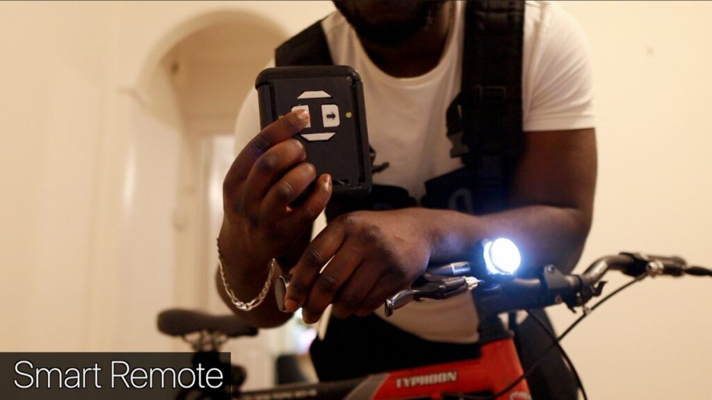
- Wireless remote to control the lights(with four fully customizable buttons)
- A Bike mount to attach to your Bike
- ON/OFF Switch Button
- Go Hand’s Free with an Inbuilt accelerometer – control Turn signals from your bike handle.
- SmartMode – Send Data and track your Journey by Phone
[/su_note]
Background Context:
LightVest was a product of the 4 Week Start-Up challenge – where I had to launch a Start-Up (somehow) in 4 weeks, with nothing but a $500 bootstrap investment.
I recommend reading the business breakdown of LightVest from a Business perspective for more context. Alternatively, watch the full Video of the Journey here:
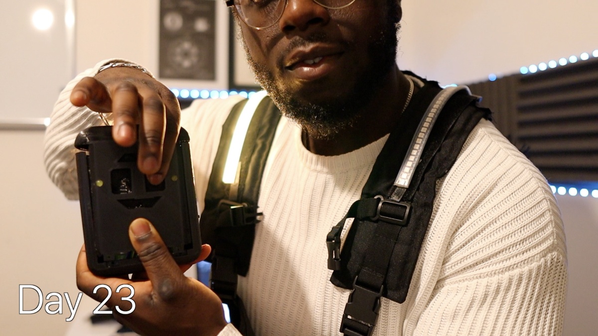
Overview of LightVest
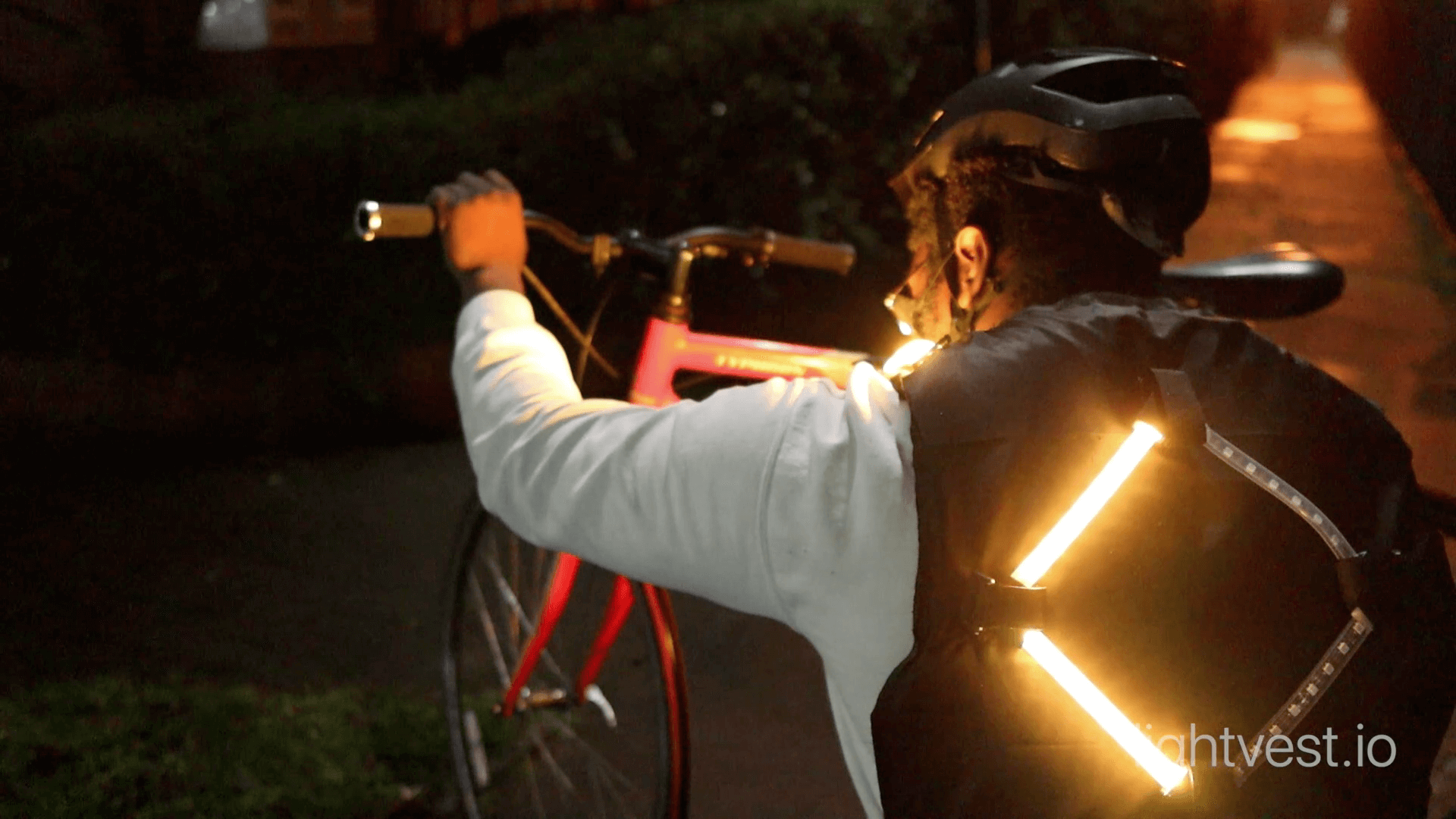
Overall, LightVest is a light strip controlled by a microcontroller safely applied to a wearable fabric, such as a vest. From this point, we can build on this idea, making it weatherproof, lightweight, portable, and even communicate with other devices.
The LightVest consist of:
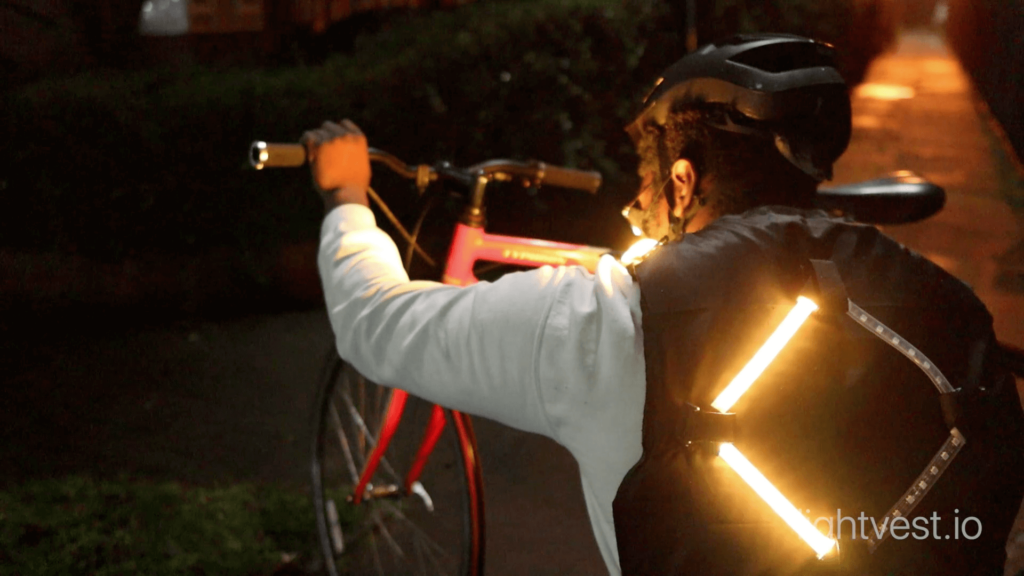
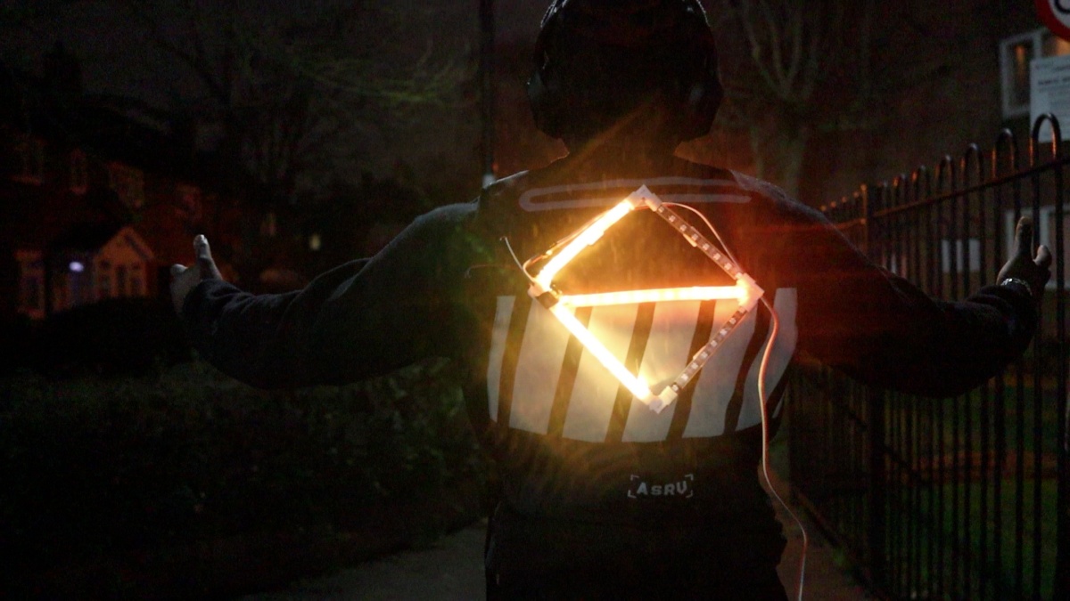
- A diamond-like indicator at the back
- Front Light Strips on Shoulders
The below table explains the functionality of each LED segment:
| LED Strip | Colour | Function |
| Diamond Strip – Half | Yellow | Turn Left or Right |
| Diamond Strip Red | Red | Abrupt Brake Lights |
| Front Shoulder Strip | Yellow | Turn Left or Right |
| All LED on Blinking | Yellow | Hazard / Emergency |
Going into detail, the Bike Remote and the LED Bike Vest have two Arduino (Microcontrollers) which communicate with each other through Bluetooth.
The LED vest works by using an Arduino to control a set of LED strips (WS2812B) based on the User’s action. The Arduino can also control individually addressable RGB LED from the LED strip.
The Bike Remote has four customizable push buttons. When a button is pressed, a value is sent to the LightVest’s Arduino, triggering the LED strip/ WS2812B to light up a specific way based on the particular value received.
Example #1:
Action: When you press the Right Button of the Remote
Communication: the value ‘R’ (representing Right is sent to the LED Vest microcontroller via Bluetooth)
Result: The LED strip would light up the right arrows of the LED strip.
But you may also be wondering, “that means you’ll need to press the remote every time you require to turn… what if I’m riding a bike?!”
This is where the gyroscope (MPU6050) comes into the picture. Using the relative position/orientation of the MPU6050, we can figure out whether the Bike is turning left or right. So, based on the same principles above, we can mount the remote to the Bike handles and do the same.
Example #2
Action: When you turn the handlebar right.
Microcontroller: The Gyroscope detects the relative change in orientation to the Right. The value ‘R’ (representing Right) is sent to the LED Vest microcontroller via Bluetooth.
Result: The LED strip would light up the right arrows of the LED strip.
You can find out more about how the accelerometer works by viewing the Robotic Arm controlled by human Gestures, which goes into more detail on this aspect.
The Part List
Parts Retailer
2 x Arduino Nano
MPU6050 (Accelerometer)
LED Strip (WS2812B)
Jumper Wires
2 x Bluetooth HC-05
2 x Slider Switch
Push Button
Capacitors
Breadboard
The Part List focuses on the Breadboard implementations of Prototype, which is ideal for development/experimenting with the vest.
Note: If you would like a more permanent implementation, Visit the LightVest Git Repo if you would like to create a PCB implementation
Note: You can apply this to any wearable vest of your choice.
How it Works – WS2812B LED Strip.
 Having a closer look, The WS2812B LED strip is made up of 5050 RGB LED lights which a smaller WS2812B LED driver is integrated.
Since it consists of RGB lights, we can control the intensity of the RGB (Red, Green, Blue) hexadecimal value to give us the Color Hue we like and which individual LEDs to light up.
The exciting part is that we can control the entire strip with just one Arduino pin from the Data line. Also, the current LED’s data output pad is connected to the next LED’s input pad.
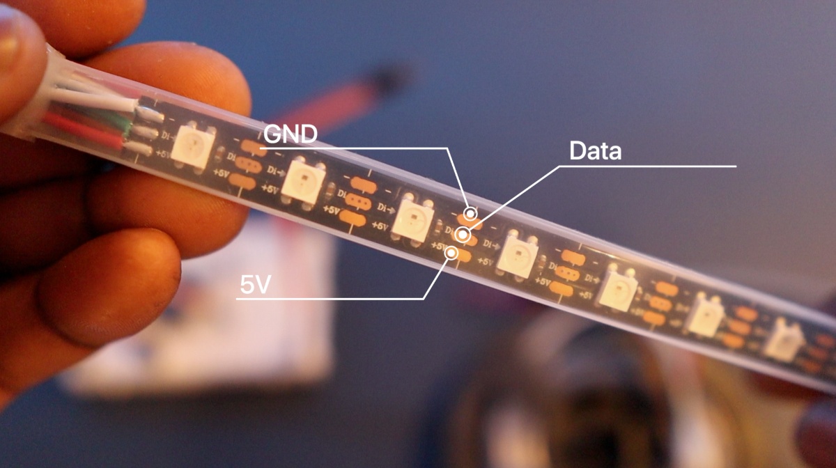
Note: Ironically (although a beauty), all LEDs rely on a single line (5V, DATA, GND). Any breakage/issues with a single LED would affect the rest of the LED.
The Breakdown of LED Lines:
- 5V
- Data (Di)
- GND
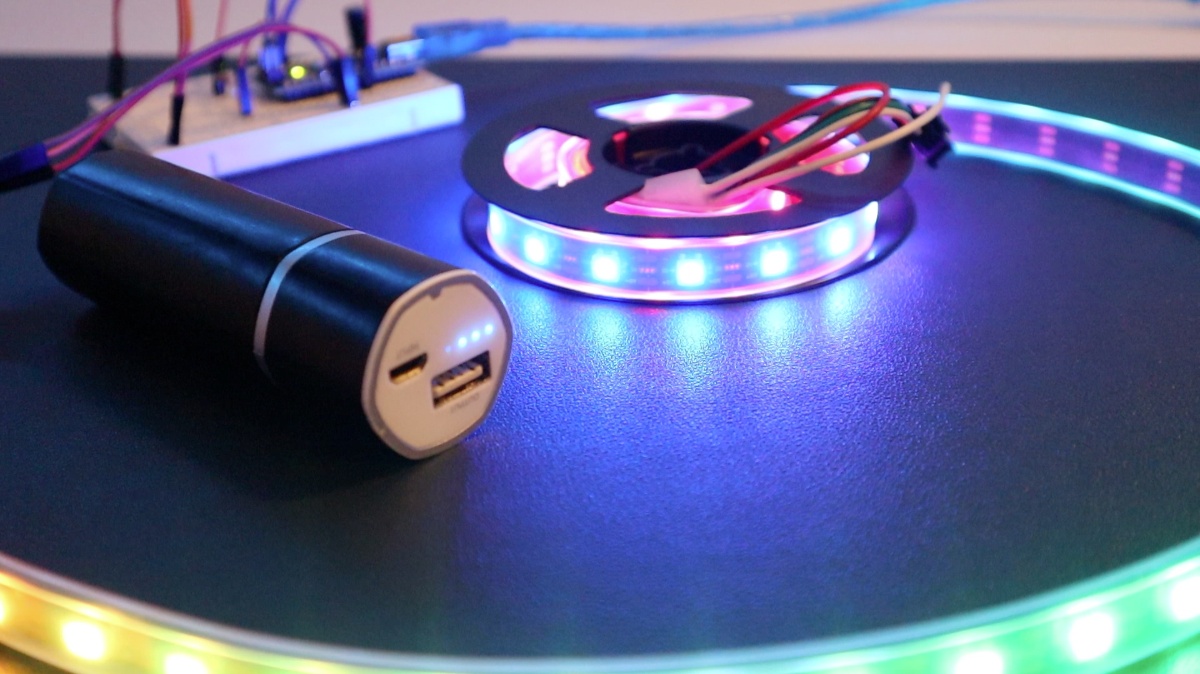
Each LED draws ~ 20mA at full brightness. Given that this LightVest has up to 90 LEDs. We’ll require ~2000maH at 5V to operate.
For a smaller number of LEDs, an Arduino 5V can handle this.
For this implementation, we’re using a 5V, 22000maH RC Battery as an external power source.
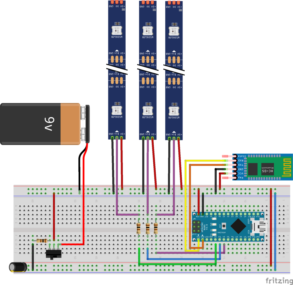
The diagram below shows the Arduino setup and the LED strips to generate a rainbow LED strip seen below.
Note: A 330 Ohm resistor was used in between the LED and strip to reduce the noise on that line to avoid glitches in the colors.
Also, a 100uF across 5V and GND (Ground) to smooth out the power supply.
Note:
- The LED strips are IP67 Waterproof protected LED strips, which can withstand a good rainstorm. However, do not try and submerge in water.
- Although the WS2812B/LED Strips are quite flexible, avoid repeated bending of the strips, this may lead to loose connections/breakage.
You can find the code for the LED strip Neo-Pixel in the example below. For more context and other uses of the LED strips, visit the Electric Skateboard with turn signal indicators.
Cutting the WS2812B LED Strips
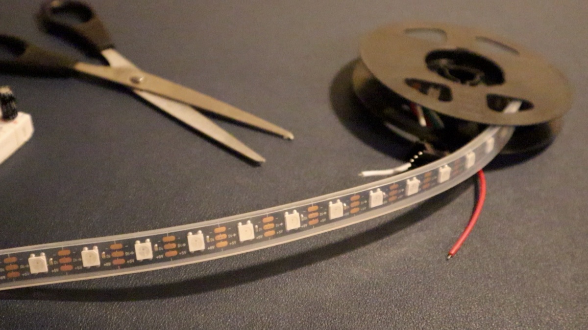
This LED strip would somehow need to be attached to a wearable clothing. However, the LED strips and Electronics would somehow need to be removable for washing. Waterproof and small enough that the electronics can safely be put in the vest.
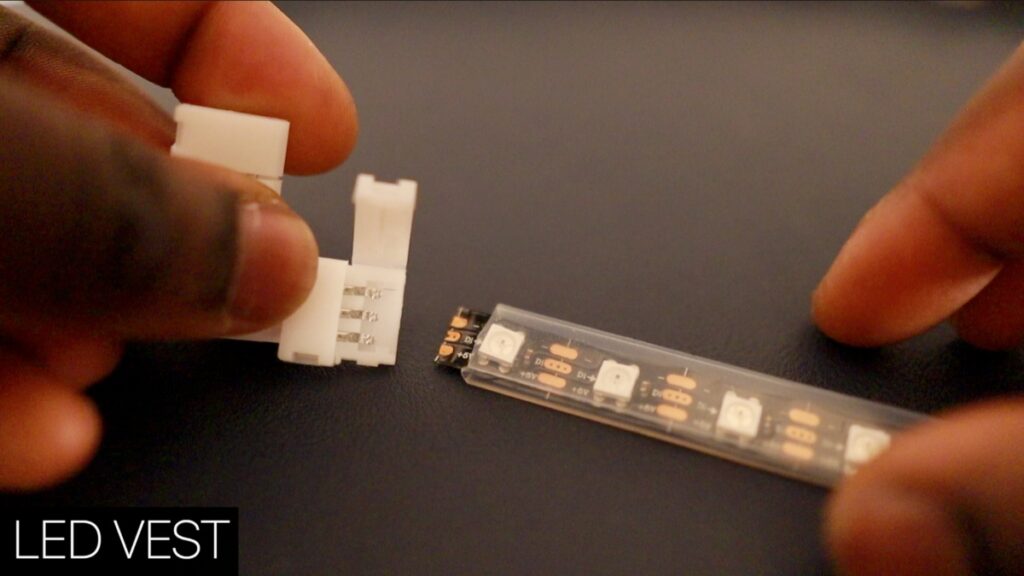
Fortunately, these are flexible LED strips that can be cut to any length and re-attached into any shape. Keep in mind there are two main ways to re-attach the LED strips:
- Soldering
- Using a clip connector
Either way is perfectly fine. However, for this version, a clip connecter was used to re-attach the LED strips since it’s a cleaner solution with a simple clip-on.
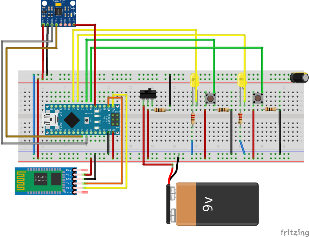
LightVest – Breadboard Implementation:
The LightVest consists of:
- LED Bike Vest – An LED Strip and am Arduino
- Bike Suit Remote – Controls the LED Strip via Bluetooth
The below diagram shows the Breadboard implementation.
Once all set up, the remote code would function as the wireless remote with the four buttons as you press one of the four buttons (each representing a direction).
The Bike Vest Remote
The corresponding LED lights will turn on, indicating that the button has successfully been pressed. As a result, a value would be sent from the remote Arduino to the Bike Vest Arduino via Bluetooth using the HC05 Bluetooth module.
The Bike Vest Suit – Overview of the Code
The LED Vest receives the value of sent from the remote. Based on the value provided:
L – Left
D – Down
U – Up
R – Right
The LightVest remote Arduino would call on the functions associated with the values received. E.g. Values ‘L’ call on stripLeft(); function
Batteries, Safety
When it comes to the LightVest, keeping safety in mind is important. As a result, a battery would be required which is small enough to fit in the Bike Vest and durable enough to withstand hard drops and external hits.
The Li-Po was an initial choice. It’s small and compact. But where it falls is that it doesn’t have much protection and can be an issue if it gets damaged or punctured.
As an alternative, a Lion RC battery pack was used as the next best alternative. It’s sturdy, durable, and can withstand harsher conditions. The only factor we have to compromise is the size. As a result, the LED remote and Suit electronics footprint would be slightly larger.
However, this is worth it to maintain a level of safety. If you have any other alternatives, do leave this in the comments.
Design – Assembly of Vest
LightVest is fully customizable and can be applied to the wearable of choice.
Note: Keep in mind to conceal any open wires and use weatherproof materials, e.g., IP67 Weatherproof Coated LED strip. And until you’re fully satisfied with the vest’s weatherproofing, avoid operating this LightVest in rainy conditions.
You can protect the circuit with a 3D printed enclosure and cover the exposed L- Connectors from a ‘Diamond shaped’ indicator with a plastic sleeve.
How were the LED strips made removable?
For this initial Prototype, the goal in mind is for the light strips to be easily detachable so the clothing can be cleaned. With this in mind, through trial and error – the best approach was to use Velcro fasteners to fasten the strips into place.
The 4 Placed Velcro fasteners can wrap around the LED indicators to hold the indicator light in place.
3D Printing and Form Factor Reduction
If you wish to 3D print the same case, you can find links to the .STL files below:
PCB Design
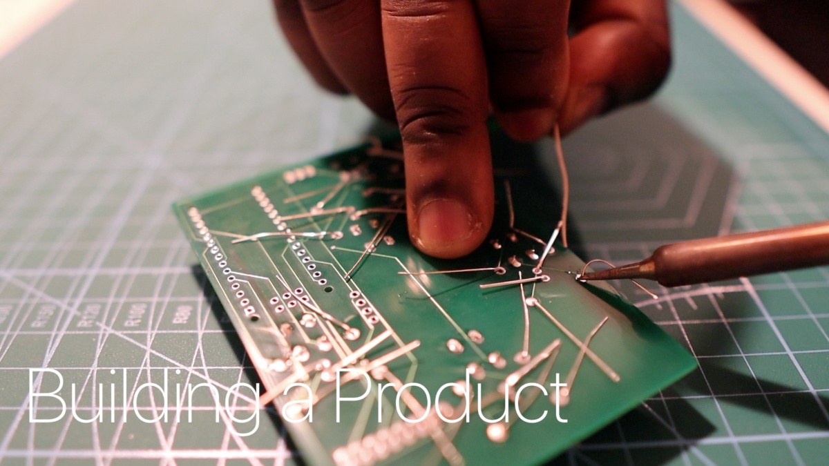
The PCB was designed to finalize what we had on the breadboard implementation and keep all the parts in place. If you would like to create your own, you can get the schematics to the Light Vest PCB here. (Fritzing & Eagle CAD Files)
Code
The below code outlines the basic functionality of how LightVest works, and how the LED strips can be programmed. As well as communicating with the remote:
LED SUIT
#include <Adafruit_NeoPixel.h>
#ifdef __AVR__
#include <avr/power.h> // Required for 16 MHz Adafruit Trinket
#endif
#define LED_BACK    5
#define LED_LEFT    4
#define LED_RIGHT   6
// How many NeoPixels are attached to the Arduino?
#define LED_COUNT 52 // Define the number of LEDs in the strip
char state = 0; // Changes value from ASCII to char
int light_delay = 50; //How long to keep the LED on for (ms)
Declare the NeoPixel strips as an Object
// Declare our NeoPixel strip_back object:
Adafruit_NeoPixel strip_back(LED_COUNT, LED_BACK, NEO_GRB + NEO_KHZ800);
Adafruit_NeoPixel strip_left(LED_COUNT, LED_LEFT, NEO_GRB + NEO_KHZ800);
Adafruit_NeoPixel strip_right(LED_COUNT, LED_RIGHT, NEO_GRB + NEO_KHZ800);
Initialize the NeoPixels and set the brightness of the LED strips. Set Serial Port at Baud Rate 9600 to start the Bluetooth communication
void setup() {
  // These lines are specifically to support the Adafruit Trinket 5V 16 MHz.
  // Any other board, you can remove this part (but no harm leaving it):
#if defined(__AVR_ATtiny85__) && (F_CPU == 16000000)
  clock_prescale_set(clock_div_1);
#endif
  // END of Trinket-specific code.
  strip_back.begin();           // INITIALIZE NeoPixel strip_back object (REQUIRED)
  strip_back.show();            // Turn OFF all pixels ASAP
  strip_back.setBrightness(150); // Set BRIGHTNESS to about 1/5 (max = 255)
  strip_left.begin();           // INITIALIZE NeoPixel strip_back object (REQUIRED)
  strip_left.show();            // Turn OFF all pixels ASAP
  strip_left.setBrightness(150); // Set BRIGHTNESS to about 1/5 (max = 255)
  strip_right.begin();           // INITIALIZE NeoPixel strip_back object (REQUIRED)
  strip_right.show();            // Turn OFF all pixels ASAP
  strip_right.setBrightness(150); // Set BRIGHTNESS to about 1/5 (max = 255)
  Serial.begin(9600);
  delay(1000);
}
Similar to the Robotic Arm implementation, In the loop section, we’re constantly evaluating if there is any new data coming from the Remote’s Bluetooth. If true, we store the incoming variable in the ‘state variable’. Depending on what value is sent this would trigger the LED strips to indicate Left, Right, Brake, or Hazard Lights.
// loop() function -- runs repeatedly
void loop() {
  if (Serial.available() > 0) { // Checks whether data is comming from the serial port
    state = Serial.read(); // Reads the data from the serial port
    Serial.print(state); // Prints out the value sent
    //Indcate Left
    if (state == 'L') {
      leftBlink();
      delay(light_delay);
    }
    //Indicate Right
    if (state == 'R') {
      rightBlink();
      delay(light_delay);
    }
  }
}
Resources
[su_note note_color=”#F5F5F5″ text_color=”#333333″ radius=”3″ class=”” id=””]<a name=”_Toc65885834″></a><strong>Features</strong>
Visit the Full Repo on Git to get access to the following:
Code
- LightVest – Bike Remote
- LightVest – Vest
Link to Schematics
- LightVest – Bike Remote
- LightVest – Vest
Diagram (Fritzing)
- LightVest – Bike Remote
- LightVest – Vest
Git Repo
- Repo with all Links
Light Vest Link: lightvest.io
[/su_note]
Conclusion
This concludes the Article write-Up. If you want to find out how the Start-Up, LightVest started, including the challenges and business pivots. Here’s the LightVest Start-Up Article.
The Purpose of LightVest is to be an open-source project that you can build and innovate on. The current version you see is V1.0. Although, it’s practical on its own. There is still quite a significant amount of room which can be improved.
Such as:
- A Smaller footprint Remote
- A Smaller footprint of wearable technology
- New design for removing the LED Strips
- Light Indication Functions
- Adding cool new features
If you would like to build your own, or contribute with more features, feel free to build on this repo. It would be interesting what further we can optimize!
[su_note note_color=”#F5F5F5″ text_color=”#333333″ radius=”3″ class=”” id=””]
And that’s all folks!
If you would like to support my projects, consider supporting my Patreon page.
Alternatively:
[/su_note]